Friday, March 15, 2013

The McGee Report on CN 4-4-0 #40 - Part 3

In 2007, Dave McGee of the Canada Science & Technology Museum prepared a comprehensive report that pulled together various sources of information on CN 4-4-0 #40 into one document.  This included a history of the locomotive specifications in its construction, references to the Portland Locomotive Works drawings, and a series of photos that chronicled the changes made to the locomotive over its life.

We continue below with Chapter 3 - Service With The Grand Trunk Railway of Canada.  

3. Service with Grand Trunk Railway of Canada.
Portland 233 was delivered to the Grand Trunk Railway as GTR 362 in November of 1872. Its road number was changed to GTR 40 in the general renumbering of GTR locomotives that took place in 1898. In this section, the engine will be referred to as GTR 362.

The large driving wheels of either 66 or 68 ½ inches indicate that GTR 362 was intended for use as a passenger locomotive.33 Beyond this, very little is known about the career of the engine. Railroad historian Ray Corley states that GTR 362 entered Canada by a roundabout route via the Albany & Niagara Falls Railway, passing over the suspension bridge at Niagara Falls.34 According to Corley, the engine was then moved to Fort Erie and restricted to the GTR tracks from Fort Erie to Stratford and St. Mary’s to Sarnia, which had been converted to standard gauge on November 8th, 1872. The remaining lines in Western Ontario were converted in October of 1873. The main line between Montreal and Toronto was converted in November. The last of the GTR’s lines, mostly in Quebec, were converted in 1874.

There is evidence that GTR 362 was in service in Western Ontario in November of 1873, when it was peripherally involved in an accident. What happened was that GTR 362 was cleared to run from Stratford to Brantford, and a second train was cleared to run behind it. A mix-up in signals led to a head-on collision between this second train and a third train traveling in the opposite direction.35

After 1874, the engine could have run anywhere on the GTR system and may have been used for passenger service in Quebec. This would explain how the engine came to the later attention of John Breakey of Breakeyville, Quebec, but there is no proof.

The only other information available concerning the engine is contained in a GTR list of locomotive stock issued in 1901. There, GTR 362 is listed as GTR 40 in an entry that gives the following information:
Table 2: GTR No. 362 as listed in 1901. 

Three items in this table stand out. One is that the engine received a new straight boiler in 1890. The second is that the engine and tender now had Westinghouse air brakes, which were not part of the original equipment.37 The third is that the engine supposedly had 68 inch driving wheels. This led Corley to suggest that GTR 362’s original driving wheels must have been replaced between 1896 and 1901.38 This would mean the GTR went to the trouble and expense of providing new wheels for Portland locomotives still on the books when they were about to be retired. It is therefore hard to accept this data. It seems more likely that the 68 inches refers to the outside diameter of the original wheels and tires, as opposed to the 66 inches for the inside diameter of the tires given in the Portland Company casting book.39

Corley also reported that the engine was adapted to burn coal instead of wood during its time with GTR. This seems very likely, but positive evidence is lacking.

3.1 The Photographic Evidence
The only other evidence  available for GTR 362 is photographic, although no photograph of the engine has been found. Appendix 6, however, contains four later photos of engines from the original batch (245, 248, and 253, and 251) which are useful.

All four of the later photos show engines with straight stacks. It is likely that 362 also received a straight stack when it was converted to coal burning (assuming that it was).

Two of the later photos show engines with a horizontal pilot (245 and 246). The photo for 245 suggests that this new form of pilot was accompanied by a new form of coupler. The earliest photo of the GTR 362 in the service of the CVR shows such a pilot. It is likely that the new pilot and coupler were installed by the GTR.

Two of the later photos (for 251 and 253) show a change in the position of the bell, which is now just in front of the cab rather than just behind the stack. The earliest photo of the GTR 362 in CVR service shows the bell in front of the cab. It is likely that the change in position took place when GTR 362 was given a new boiler in 1890.

The photos continue to show a tender with flared out tops along the sides, and scallops at the front.

The McGee Report on CN 4-4-0 #40 - Part 2

In 2007, Dave McGee of the Canada Science & Technology Museum prepared a comprehensive report that pulled together various sources of information on CN 4-4-0 #40 into one document.  This included a history of the locomotive specifications in its construction, references to the Portland Locomotive Works drawings, and a series of photos that chronicled the changes made to the locomotive over its life.

We continue below with Chapter 2.5 - Related Photographs.  

2.5. Related Photographs.
It was Portland Company practice to take a photograph of its locomotives when they were completed. No photo of Portland 233 has been found. However, many photos of related engines have been located, including nine photos of Portland engines delivered in 1873, of which five are from the same batch as Portland 233. The photos from the same batch include shop numbers 238, 244, 245, 251, 253.  The additional photos are of shop numbers 246 and 248, built in between the two parts of the 233 batch, as well as shop number 254, built right after the batch, and 272 which was built for the GTR. These photos are found in Appendix 6 and on the DVD.

Not all the pictures are from the same decade. Nevertheless, a number of conclusions can be reached about the original appearance of Portland 233.

To begin with, most of the pictures show a “vertical pilot” with vertical rails. Two show a “horizontal pilot” with horizontal rails (shop 246 and 245), but one of these is a non-GTR engine and the other is a much later photo. It is most likely that Portland 233 had a vertical pilot. However the casting list does refer to "horizontal bars" in connection with the timber for the pilot.30

All the early pictures show a diamond stack, rather than a mushroom stack (with the exception of shop 246). Three later photos show a straight stack, but these appear to be later modifications. It is most likely that Portland 233 had a diamond stack.31

All the earliest photos show the bell, sandbox and steam dome, in that order, with the bell at the front of the boiler. It is likely that Portland 233 had this configuration.

Several early photos show bright-work, fancy painting and shiny brass bands. It is likely that this was also true of Portland 233.

All of the images of trains from the same batch show round arched windows on the side of the cab. It is likely that Portland 233 shared this feature, although other Portland engines delivered to the GTR in 1873 had square windows (for example 246 and 272). The photographic evidence seems incontrovertible, particularly since the first known photo of Portland 233 (as CVR 40, see Appendix 6) shows round arch windows. The visual evidence is in direct conflict with drawing 1501P, which states that it is a drawing of the cab for many engines, beginning with Portland 191 and including Portland 226-245. Notably, drawing 1501P is not given in the casting list.32

Most of the images show solid truck wheels on the engine and the tender. This was likely true of Portland 233.

All the earliest photos of GTR engines show tenders with sides that are flared out at the top and have a slight scallop at the front. Portland 233 likely had a tender with these features. 


Go to "The McGee Report - Part 3".  "Chapter 3. Service with Grand Trunk Railway of Canada".

Back to "The McGee Report on CN 4-4-0 #40 - Part 1"

Thursday, December 27, 2012

The McGee Report on CN 4-4-0 #40 - Part 1

In 2007, Dave McGee of the Canada Science & Technology Museum prepared a comprehensive report that pulled together various sources of information on CN 4-4-0 #40 into one document.  This included a history of the locomotive specifications in its construction, references to the Portland Locomotive Works drawings, and a series of photos that chronicled the changes made to the locomotive over its life.

we present below Part 1 of the report
The link below will take you to a copy of this report.
http://www.railwaybob.com/cn40report.pdf
It's a huge report so be patient.  When it downloads, change the viewing size to 100%. 
Canadian National 4-4-0 #40
A Preliminary Report on the Known Documents

Prepared for the Canada Science & Technology Museum
by David McGee
Table of Contents
1. Introduction, p. 2

2. Construction by the Portland Company, p. 4
    2.1 Related Contract Specifications, p. 6
    2.2 The Portland Company Casting Books, p. 9
    2.3 Portland Company Drawings, p. 12
    2.4 Related Elevations, p. 13
    2.5 Related Photographs, p. 15

3. Service with the Grand Trunk Railway, p. 17
    3.1 The Photographic Evidence, p. 19

4. Service with the Chaudiere Valley Railway, p. 20
    4.1 The Photographic Evidence, p. 21

5. Service with Canadian National, p. 22

6. At the Canadian National Museum of Science and Technology, p. 25

7. Further Research, p. 29

Appendix 1 - Portland Company Locomotive Production
Appendix 2 - Portland Company Locomotives Built for GTR
Appendix 3 - Portland Company Contract Specifications
Appendix 4 - Portland Company Casting List for Engines Nos. 229-245 and 251-253
Appendix 5 - Drawings Related to Portland 233
Appendix 6 - Photos Related to CN 40
Appendix 7 - Contents of the DVD

1. Introduction:
In 1967 the Canadian Science and Technology Museum (CMST) acquired a steam locomotive now known as Canadian National (CN) 40. This engine was built in 1872 by the Portland Company of Portland, Maine, for the Grand Trunk Railway of Canada (GTR). The Portland Company's shop number for the engine was 233. Its original road number was GTR 362 and changed to GTR 40 in 1898.   This number was kept by lumber Baron John Breakey, of Breakeyville, Quebec, when he bought the engine from the GTR in January of 1903. CN kept the number when it acquired the engine from Breakey’s Chaudiere Valley Railway (CVR) in 1947 or 1949.1

CN 40 is believed to be the only surviving Portland Company 4-4-0, a type of locomotive that was the standard North American engine of the nineteenth century. CN 40 is also the oldest surviving passenger locomotive of the GTR, Canada’s first major railway system, making it the oldest surviving passenger locomotive in Canada. Literally millions of people saw CN 40 during the 1950s when it was part of CN's traveling “Museum Train”. Many more saw the engine when it was on display at the CMST exhibition building in Ottawa.2

Several attempts have been made to gather information about CN 40, but without much success.  In 2007, however, the CMST decided to make a concerted effort to document the engine in order to be able to interpret the locomotive as it now exists, and possibly to restore it,.

This report presents the first results of the renewed attempt to document CN 40. It is based on archival research carried out between May 1 and July 31 of 2007. The goal of this research was to collect and digitize as much evidence about the physical history of the engine in the time available. It was not intended to interpret the existing engine in light of the information gathered, but it has proven necessary to offer various interpretations of the evidence gathered. 

The evidence is presented below in sections corresponding to the phases of construction and ownership of CN 40, beginning with its building by the Portland Company and continuing with the years it was owned by the GTR, the CVR, CN and the CMST. The section concerning construction is by far the longest. It contains the first comprehensive collection of information about CN 40 ever assembled. The following sections deal for the most part with photographic evidence. Some tabular data has been placed in the text. Most of the detailed tabular data appears in the Appendices. Almost all the documents referred to, as well as this text, are provided in digital form on the accompanying DVD.

A great deal has been learned about CN 40 during this initial phase of investigation. But it is also clear that much has been lost. Various scholars, archivists and annotators have said things about CN 40 for reasons that are no longer evident. Documents that once existed are now missing. There is, however, good reason to believe that many of the missing documents still exist. Hopefully, the information contained in this report will not only contribute to a better understanding of CN 40, but will alert other investigators to the potential significance of the “lost” documents when they come across them and encourage them to make this information known to both the railway history community and the CMST.

2. Construction by the Portland Company.
As noted in the introduction, the steam locomotive known as CN 40 was constructed in 1872 by the Portland Company of Portland, Maine, for the Grand Trunk Railway of Canada. Its Portland shop number was 233. It was delivered to the GTR on November 27th, 1872 as GTR number 362.3 Since Portland’s records are organized in terms of shop numbers, the engine will be referred to in this section as Portland 233.4

The Portland Company was founded by John Alfred Poor (1808-1871) in 1846 to build railway equipment. The company produced 631 locomotives between 1848 and 1906. Almost all of these engines were built before 1895.5 Most were of the 4-4-0 type, with four leading wheels, four driving wheels, and no trailing wheels, which was the standard type of locomotive used by North American railways between 1850 and 1898, after which they were rather quickly phased out.6 The Portland Company also built marine engines, marine boilers, and many other kinds of machinery, and stayed in business until 1982. Much of the company's historical material was donated to the Maine Historical Society (MHS) in the 1960s.7 

Of the 631 engines produced by the Portland Company, 259 were made for Canadian railways, accounting for approximately 41 per cent of total output. One hundred and nineteen engines were built for the GTR, making the GTR Portland’s biggest Canadian customer.8 Some of these orders may have resulted from the special relationship between the GTR and Portland, which became the eastern terminus of the GTR system in 1853.9 The GTR maintained large shops and yards there.10

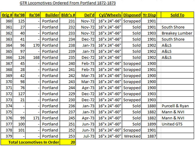
The first Portland engine built for the GTR was delivered in 1854. Forty-two more engines were delivered by January of 1872, all but three of which were the "wide" or "colonial" gauge of 5 feet, 6 inches (66 inches altogether).11 It was in 1872, however,  that the GTR decided to convert all its existing track to the standard North American gauge of 4 feet 8 1/2 inches (56 1/2 inches altogether).12 As a result, the GTR was suddenly in need of a large number of standard gauge locomotives. Accordingly, Portland 233 — the future CN 40 — was one of a batch of 22 almost identical standard gauge 4-4-0s ordered from the Portland Company by the GTR in late 1871, or early 1872. Delivery of these engines began in November of 1872 and continued into 1873 as more orders from the GTR poured in.13 See  Table One. 

2.1 Related Contract Specifications
One assumes the process of ordering new engines began with some sort of correspondence between the GTR and the Portland Company concerning the number of engines wanted, the need for variations based on experience with previous engines, the availability of new technology, and so on. No such correspondence concerning Portland 233 has been found.

The next step in the process of ordering was the drafting of a contract to which a specification was attached. No contract or specification has been found for Portland 233, or for any other engine in the batch. However, two examples of the kind of contract and specification that would have been made can be found in the National Archives of Canada (NAC). Two more contract specifications are in the archives of the Canadian Railway Historical Association (CRHA) at Exporail in Brossard, Quebec.

Of the documents in the NAC, one is a handwritten draft of an agreement to convert a number of existing wide-gauge engines to standard gauge.15 The second is a contract for 11 new engines, dated July 21, 1874.16 This second contract states that the new engines were to be delivered by September 20th, 1874, and mentions a few physical details: for example, that they should have Smith Vacuum Air Brakes on the tender and driving wheels, and that the headlights should be of an approved pattern with a reflector of 22 inches diameter. The contract is accompanied by a detailed specification, written out on a pre-printed form provided by the Portland Company. Attached is a handwritten note asking for items like screw jacks and jack bars, hammers, torches, and oil cans. These documents confirm the fact that ordering normally began with documents that went back and fourth between the two companies before they were formally printed and signed. 

The documents in the CRHA consist of the pre-printed specifications that would have accompanied a complete contract package.17 There is no indication of what locomotives they refer to. The first specification is for an “eight-wheel” coal burning engine, dated Dec 16, 1872 (just after delivery of Portland 233), and was apparently ordered by an American railway.18 The second specification is for an "eight-wheel," “wood or coal burning” engine and dated to June 10th, 1874. The second document states that the tires for the driving wheels were to be made to GTR standard sizes and gives the tank capacity in Imperial gallons, so this order is almost certainly for a GTR engine. However, the document is dated more than a year and a half after Portland 233 was delivered.

Although neither of the CRHA documents specifically concern Portland 233, they represent the nearest known specifications in terms of date, and are therefore important. A detailed comparison of their contents is made in Appendix 3. The details show that the earlier engine was to have 16 by 24 inch cylinders, boiler tubes made of iron, and weigh 32 tons when fired and ready. The later engine was to have 17 by 24 inch cylinders and boiler tubes made of steel, which allowed an increase in the number of boiler tubes from 145 to 162, as well as several other minor changes in an engine estimated to weigh 34 tons, fired and ready. As Appendix 3 shows, however, in almost all other respects the two specifications are more or less identical as to the dimensions and the materials to be used. 

The similarity between the two specifications is important because it is an indicator of the slow rate of design and/or technological change in locomotive construction at the Portland Company. This slow rate of change means that evidence from many different locomotives may be relevant to the understanding of Portland 233. Portland 233 resembled the engine in the earlier specification more than the later engine but — with caution, of course — both specifications can be used as aids for interpretation.

2.2 The Portland Company Casting Books
Once an engine was ordered, the Portland Company's next step was to prepare a detailed list of the parts and materials needed. The list was copied onto printed forms in the company’s "casting book," which covered (in order):
  • Iron castings for the engine;
  • Iron castings for the tender;
  • Brass and “compo” castings for the engine;
  • Iron forgings for the engine;
  • Iron forgings for the tender;
  • Plate iron for the boiler;
  • Plate iron for the tank;
  • Miscellaneous iron for the engines,
  • Tubing and etc. for the engine;
  • Timber for the tender; and 
  • Timber for the engine.

As the list shows, more than castings were included in the casting books, where some 500 specifications could be made for each engine. The casting books provide the single biggest source of detailed information for any Portland engine.

The data for Portland 233 is found in Casting Book, Volume 15, which contains a list of the specifications used for shop numbers 229 to 245 and 251-253. A full transcription of the casting book may be found in Appendix 4.19

Original entries in the casting book were made in blue ink. These entries give the dimensions and/or the materials of various parts, and are sometimes accompanied by very small drawings. Later annotations were added in pencil, but it is not known by whom. The hand looks modern, and annotations in the same hand appear to have been made to all the casting lists at about the same time.

One of the peculiar features of the casting book is the inclusion (in blue ink) of what will be called the "same as" numbers for various parts. The first entry for the Portland 233, for example, states that the boiler saddle is the "same as 152." The next entry states that the cylinders and pistons are the "same as 153, 155." The majority of entries in the casting book have these "same as" numbers, while some are blank and others are stated as being "same as the draught." The “same as” numbers turn out to be the shop numbers of earlier engines. The saddle of 233, for example, is identified as being the same as the saddle of shop number 152, while the cylinders and pistons are identified as being the same as the cylinders and pistons of shop numbers 153 and 155.

The earliest "same as" number in the casting list for Portland 233 is 112, an engine delivered to the New York and Boston Railway in April of 1864. The latest "same as" number is 222-225, which refers to a batch of engines that were ordered by the GTR before Portland 233, but delivered at various times in late 1873 and early 1874.20 The "same as" numbers help confirm the point made above about the slow pace of technical change in the locomotives built by the Portland Company. An engine like Portland 233, for example, incorporated parts that were originally designed more than six years and 100 Portland engines earlier.

The data in the casting list confirms the similarity between Portland 233 and the contract specification dated December 16, 1872, beginning with the fact that Portland 233 also had a 48-inch diameter boiler and 16 by 24 inch cylinders. A more detailed comparison of the specifications is out of place here, but confirms the similarity as to both dimensions and materials.

The casting book also reveals differences between engines in the same batch. The list says, for example, that the drivers for Portland 231-237 and 251-253 were to be 5 feet 2 inches in diameter (or 62 inches total), while the wheels for the other engines in the batch were to be 4 feet 8 inches in diameter (56 inches total).21 Dimensions for the tires are given as 5 feet 6 inches in diameter (or 66 inches total) for engines 231-237 and 251-253, and 5 feet diameter for the other engines. The tires were to be 2 ½ inches thick. It is not clear from the casting list whether the dimensions of the wheels and tires are for the inside or the outside diameters. The numbers do not add up directly.22

Given the different size of driving wheels for different engines in the batch, there was a corresponding difference in the size of truck wheels. The casting book states that the truck wheels for Portland 231-237 and 251-253 were to be 30 inches in diameter, and 28 inches for the other engines.23 The wheels of the tenders are given as 33 inches in diameter, so the tender was originally higher than the engine truck. Naturally, the pilot for the engines with the larger wheels was bigger than the pilot for the smaller engines. Interestingly, the data for the pilot is contained in the section of the casting list that is for timber to be used in building the engine.24
   
2.3 Portland Company Drawings
Originally, the casting books contained no direct references to drawings. However, before any engine could be assembled, the right drawings had to be found so that the right castings, forgings and other parts could be made.25 This suggests that there was once some sort of registry relating the "same as" numbers to the drawings for required parts. 26 This registry can no longer be found.27

Fortunately, the pencil notations added to casting book Vol. 15 give the drawing numbers for many of the parts of Portland 233. Better still, these drawing numbers appear to be quite accurate. Each number leads to a drawing for the expected kind of part. All but two identify the correct part for the correct engine, according to the "same as" number. For example, drawing 1187P is indeed for the cylinders of engines 153 and 155, while drawing 1619P is indeed for the main valves of shop numbers 188 and 189. The "P” means the drawings were made on paper. Other drawings, designated "L" were made on linen. A complete list of drawings relating to Portland 233 is given in Appendix 5.28

In several cases the pencil notes identify drawings of parts for which no "same as" number is given in the casting book, or for parts that are described as being the same as the draught. In these cases, it is not possible to vouch for the absolute accuracy of the information, except to say that the majority of the other drawing numbers are correct, and they all appear to have come from some sort of registry.

Another oddity of the casting books is that several parts are identified as being the “same as” those of earlier engines, but the date on the actual drawing is not only later than the engine referred to, but later than the delivery of Portland 233. This indicates that drawings for various parts were reused many times over the years, then re-drawn once they wore out, but not updated to reflect the number of the latest engine for which they were used. This is likely because the missing drawing registry, like the casting books, referred to the drawings by their “same as” numbers.   

A detailed analysis of the drawings of Portland 233 is beyond the scope of this report.

2.4 Related Elevations
The Portland Company generally produced an elevation for each of the locomotives or batch of locomotives it built, showing the completed engine from the side. No elevation for Portland 233 or for any other engine in the batch has been found. If fact, almost all of the elevations for engines built at this time are missing. This may be because the elevations, of little use during construction, were really made as presentation drawings to be given to the customer at the time of delivery.

Nevertheless, the Portland Company archives do contain several elevations that may be useful. They are listed in Appendix 6, and digital copies are found on the DVD.

Drawing 144P is for Portland shop numbers 153-155, and dated April 9, 1859.  These engines were built for the GTR and are the engines most often cited in the “same as” numbers for Portland 233.29

Drawing 1914P is for Portland 147 and dated November 26, 1867. This engine was built for the Portland & Rochester Railway. This elevation is among the most detailed available.

Drawing 1901P is dated May 19, 1868 and was made for Portland engines 142-146, which were built for the GTR. This is the nearest elevation of an actual GTR engine to the date of Portland 233, although it is not referred to in the casting book.

Drawing 1933P is for Portland 156, dated May 7, 1869. This engine was built for the Maine Central, and is referred to in the casting list.

Drawing 1960P is for Portland 196 and dated November 11, 1871. This engine was built for the Portland and Ogdensburg Railway. This is the nearest elevation to Portland 233 in date.

Drawing 23058L has no date, but shows Portland 352, delivered to the Maine Central in June of 1879. This is the first extant elevation for a Portland engine after Portland 233.

Drawing 196P is for Portland 394-395 and dated August 17, 1881. These engines were built for the Maine Central. The drawing helps to show the continuing similarity of Portland output.

Go to "The McGee Report - Part 2".  "Chapter 2.5 - Related Photographs"

Tuesday, October 16, 2012

What's Possible?

Restoration Work On CN #40 - A Conundrum!
(Conundrum - a question having only a conjectural answer; an intricate and difficult problem.)

We have been asked to come up with our vision of what CN #40 might look like on a cosmetic restoration.  We are, however, handicapped as we do not know the condition that each element of the locomotive is in.

For example, suggestions have been made on how to "restore" the cab as the top sills of side cab windows were originally curved whereas they are currently straight.  However, an examination of the cab indicates that the top sills are covered by two pieces of sheet metal that are screwed into the cab wall.  Photos in the Bailey & Glithero report indicate that this may have been done during its tenure with the Chaudiere Valley Railway. A cursory examination of the cab indicates that it is a complex amalgam of wood, steel rods, window sashes and other elements.  What would be involved in "restoring" the top sills to their "original" condition. 

Comments have been made that the wooden pilot is not "typical" in that most pilots were made of tubular steel and that the pilot should be replaced.  However, close examination of photos of the pilots of 4-4-0 locomotives, including Grand Trunk, indicate no rivets on early pilots.  There are also stories of locomotives hitting animals with the pilot being shattered into a thousand splinters.  Perhaps the pilot is "typical" and should stay where it is?  (A subsequent review of the appendices attached to the McGee report indicates the pilot was definitely made of wood.)

Major parts of the valve gear are missing.  Some parts have been found with the possibility of installing them on the locomotive.  However, if the locomotive is moved, how will this impact the valve gear in the steam chest?  Are these parts free-moving or are they all seized up?

There are other items that require examination before decisions can be made on how the restoration should proceed.

Preliminary Work Needs To Be Carried Out
This does not mean, however, that studies should be done before ANY work is undertaken on CN #40.

  • We have started with needle-gunning and wire-wheeling the firebox and boiler.  There is other rust-removal work that needs to be done.
  • The paint on the cab has peeled.  As a minimum, the paint should be stripped, a job that should be relatively easy, and new paint applied. 
  • The condition of the valve gear in the steam chests needs to be examined to determine if the gear is free-running or seized.
  • There is residue in the bottom of the smokebox.  The nature of this material needs to be determined and steps taken to remove it.
  • The boiler tubes are plugged with soot and grime.  These need to be cleaned.
  • The smokestack has not been examined to determine whether it can be readily modified or even if the original smokestack rests inside.  The smokestack should be examined.
  • There are a large number of loose parts throughout the buildings.  These need to be gathered, catalogued, their condition determined, and new parts fabricated if deemed necessary.
  • ...... and a whole lot more preparatory work done.

What should CN #40 Look Like In Its Restored State??
I have no idea as to what CN #40 should look like in its restored state.  After looking at what was done to CP #374, I'm leaning towards restoring CN #40 back to its Museum Train days as being the most feasible.  And if I were to go further, I'd be taking a close look at the likes of similar locomotives like CPR 4-4-0 #71.
 However, there are a number of items that have to be considered before arriving at a definite answer.

We don't know what the condition of the various elements are like.  For example, do we need to replace the cab?  If yes, how difficult would it be to replace the cab?  Do we have the expertise, time, and money to replace the cab.  Is the current cab, in fact, not an "original"?

We don't know what a "typical" Grand Trunk locomotive might have looked like during the period that CN #40 was in operation.  Doing some of the preliminary work and analysis listed above would help us to decide what we would like to have done.  For the moment, we have more than enough work to keep us busy working on CN #40 for quite a number of weeks.

Bob Moore. 

Conservation Considerations

Bailey & Glithero - Suggested Restoration Options
We have been asked to come up with our vision of what CN #40 should look like if it was to be restored.  Seven scenarios are presented in the Bailey & Glithero report:

  1. Continuation of its present form for static display.  This involves cleanup and repainting of the locomotive and the addition of missing components (eg ash pan damper arms, eccentrics, missing valve gear, etc)
  2. Return to its 1950 restored condition - This is a continuation of the above option with the removal of the knuckle coupler to be replaced by link-and-pin, 
  3. Return to its c1925 - c1947 form for static display.  This option involves major modifications to the locomotive with the removal of the existing wooden pilot to be replaced possibly by a switcher pilot, reducing the height of the smokestack, substituting a proper period knuckle coupler, etc.  I don't recommend this option for reasons stated below. 
  4. Return to c1925 - c1947 working condition.  This option is discarded as being next-to-impossible.  I agree.  
  5. Return to its 1903 - c1925 form for static display - This involves modifications to the cab, substituting a proper period Westinghouse air brake pump, major modifications to the tender.  I don't recommend this option for reasons stated below.  
  6. Return to its 1890 - 1903 form for static display - Bailey & Glithero consider this option to be a continuation of the previous option.  This involves further major modifications to the locomotive.  They indicate that this would present the locomotive as being representative of a "true" (my word) Grand Trunk locomotive.  They don't, however, define what such a locomotive might look like.  We discuss this in further detail below.  
  7. Return to its 1872 - 1890 form for static display.   Bailey & Glithero are of the opinion that this was apparently in the mind of CN in its 1950/51 modifications to the locomotive in preparation for its role in CN's Museum train.  They are of the opinion that, if this option were to be considered, efforts would be better directed towards building a complete replica locomotive.  This opinion is presented without any form of evidence as to why it would not be possible to do so.  
Restoration Limitations
Whenever undertaking any type of work, the major consideration has to be whether the persons undertaking the work have the capabilities, the time, the talent, and the money to do so.  This is also true for restoration work.  Some of the options presented above are well beyond the capabilities of even the most talented museum restoration staff.

Options 3, 4, 5 and 6 require major modifications to the locomotive.  For example, the current wooden pilot would be removed and replaced with a new pilot fabricated from tube steel.  Aside from trying to answer the question "What type of steel pilot - vertical, horizontal, or switcher?", no study has been done to determine the type of work that would need to be done to implement these options.  A cursory examination of the cab walls indicates that it is a complex amalgam of wood, steel rods, sheet metal covering up unknown features, to say nothing of the way that it is fastened to the steel floor.  Bailey & Glithero have offered up options, however, we do not have the benefits of detailed analyses to determine how feasible these options might be.

Option 5 requires major modifications to the tender.  This involves fabricating, shaping, and riveting large sheets of steel, to say nothing of the work required to "peel back" the existing steelwork, the cost of materials, and the time required to make these modifications.  In my opinion, this option is well beyond the capabilities of even the most talented museum restoration staff, to say nothing of the time and cost that would be required to carry out this modification.  

For this reason, I consider Option 3, 4, 5, and 6 as NOT being feasible.

However, before considering Options 1, 2, and 7, we are missing major components to arrive at an informed decison.  We have no indication as to the scope and type of work that needs to be done.  We have no idea as to what CN #40 might have looked like during these time periods.  Before arriving at a decision on how we want to "restore" CN #40, we need to make further examinations of both the locomotive and what other Grand Trunk and 4-4-0 locomotives might have looked like. 

"Models" For CN #40?
In conducting my analysis of the situation, I examined photographs of 166 4-4-0 steam locomotives covering the period from 1861 to the end of steam.  This included photos of CN #40 in its Museum Train regalia.

 In reviewing these photos, it became clear to me of the vision that CN had for the restoration of CN #40.  The most famous 4-4-0 at the time of restoration was Canadian Pacific's "Countess of Dufferin" on display outside their train station in Winnipeg.  The prominent features of this locomotive are its wooden pilot and balloon smokestack.  Except for the presence of a 3rd dome, and the location of the bell and steam dome, the two locomotives are very similar. 
Another model for CN #40 at that time was CPR 4-4-0 #374.  Built by Canadian Pacific in 1886, this locomotive brought the first transcontinental train into Vancouver on 23 May 1887.  It was finally retired in 1945 and put on display in Kitsilano Park in Vancouver.   
The locomotive was restored in time for Vancouver's Expo 86 and is currently on permanent display in the Engine #374 Pavilion at Davie & Pacific Blvd.   
CPR #374 represents the possibilities of what a locomotive restoration project might look like.  Further information on CPR #374 can be found at the end of this link

There are major similarities between CN #40 and CPR #374.

What Does A "Typical" Grand Trunk Locomotive Look Like?
No locomotive ever stayed the same from the time it emerged from the builders until the time it was scrapped.  Clegg & Corley demonstrate this very clearly on Page 30 of their seminal book "Canadian National Steam Power.  A photograph of Grand Trunk 4-6-2 #1510 (later CN #5294) is shown at Belleville, Ont soon after construction in 1918.  Below this photo is another one of CN #5294 taken many years later.  A feedwater heater has been added, the pilots have changed, the piping around the water pump is entirely different, in addition to other modifications.

Bailey & Clithero's report indicates that even CN #40 underwent major changes throughout its operating life to say nothing about those changes that are not indicated in their report.  In our previous post, we included photos of "typical" Grand Trunk locomotives.  Here are a few more.


A "typical" Grand Trunk locomotive could look like many of the above and other 4-4-0 locomotives.  For CN #40, it's not a matter of "What would you like it to be?".  Rather, it's what is it possible to do. 

Features & History of CNR 4-4-0 #40

A bit of history of Canadian National's 4-4-0 #40.

Grand Trunk Locomotive Order With Portland Locomotive Works
CN #40 was part of an order of 20 locomotives placed with Portland Locomotive Works of Portland, Maine by the Grand Trunk Railway (GTR) and delivered between November of 1872 and July of 1873.  The locomotive was delivered as #362 in a numbered range of #360 - 379 with builder's #233 in a numbered range of #231 to #253. 

While builder's #246 - #248 were assigned by Portland to non-GTR locomotives, #249 and #250 were assigned to GTR #325 and #326 - two 4-4-0 locomotives with 60" drivers and 16"x 24" cylinders - which were delivered in May of 1873. 

The main features of these locomotives were their 66" drivers and 16"x 24" cylinders.  A scan of GTR locomotives built before, concurrent and after this time period indicate that these features appear to be standard with driving wheels being 60" or 66" in diameter and cylinders being 16"x 24" or 16"x 26".

GTR locomotives went through renumberings in 1898 and 1904.  In the 1898 renumbering, GTR #362 received GTR #40.  The only locomotives in the original order that survived into the 1904 renumbering were #364 (#170), #366 (#168) and #376 (#171).  All others had been scrapped or sold.  (Andrew Merrilees Collection, Library & Archives Canada, MG31 Series A10, Volume 19, Handwritten Notes "GTR Locomotives", Pages 43 & 44)

While there are no photos of #362 during this time period, a photo of #271, built in 1874, might give us an idea of what our locomotive looked like at that time. (The date of the photograph is unknown.) 
The main features of #271 are its 16"x 26" cylinders and the 60" driving wheels.  The locomotive is equipped with a wood-burning smokestack as evidenced by the logs protruding from the tender.

Another photograph from the Maine Memory Network shows a Grand Trunk 4-4-0 photographed circa 1875.  There appears to be a load of coal in the tender

Except for the smokestacks, the placement of the steam and sand domes, and the curved side-cab windows, the locomotives are cosmetically very similar in many respects to #362 (#40) in its current form. 
Sale to Breakey Lumber/ Chaudiere Valley Railway
In 1903, #362 (#40) was sold to Breakey Lumber of Chaudiere Mills (formerly Breakeyville) in Quebec's Beauce Region, about 90 km southwest of Quebec City.

In 1846, Hans Denaston Breakey, an Irish immigrant, established the first of several saw mills in partnership with his brother-in-law, Charles King.  In the spring of 1847 they initiated yearly timber drives on the Chaudière between the southern Beauce and Chaudière Mills which would continue uninterrupted until 1947. At the height of the timber drives during the 20th century the firm would employ up to 2,000 men each spring.

With the retirement of his father, John Breakey assumed control of the business in 1870.  Initially, oxen and horses hauled the timber from Breakey’s mill to New Liverpool (Saint-Romuald) on the St Lawrence River, where his firm had docking facilities. There it was loaded on schooners for shipment to Quebec City and then overseas. In 1883 Breakey built a six-mile stretch of railway from his mill to Chaudière-Bassin, close to New Liverpool. In 1898 he and other members of his family incorporated the Chaudière Valley Railway Company. The proposed line was to run along the Chaudière from Scott-Jonction (Scott) to Chaudière-Bassin so as to incorporate the section already in operation and then to continue past Lévis to a terminus at deep water.  This part was never built.

By 1895 Breakey employed 600 men and 300 horses in the lumber camps during the winter; 200 men and 20 horses worked at the mill and elsewhere during the summer. The mill processed 33,000,000 board feet of lumber per year into beams, planks, laths, railway ties, and telephone and telegraph poles. About ten years later an historian of the lumber industry, James Elliott Defebaugh, described Breakey’s mill as “one of the largest if not the largest spruce deal mill in the province of Quebec.” 

With the death of John Breakey in 1911, the family began production of pulpwood and in 1922 they completely abandoned the manufacture of sawn lumber.  In 1947 they added a groundwood mill to their facilities. (Dictionary of Canadian Biography Online - John Breakey)

It was usually the case that industrial operations such as Breakey Lumber would purchase used locomotives from the railways or from the scrap dealers for their railway operations.  Very rarely were locomotives purchased new from the builders.  Such was the case with Breakey Lumber when they purchased GTR #362 (#40) in 1903.  At that time, GTR #362 (#40) had been in service for 31 years.  Aside from minor maintenance, these industrial locomotives very rarely had major overhauls, except for those that would keep the locomotive operating.  Bailey & Glithero indicate that its truck and tender wheels were replaced in 1925, along with its tender tank and a Westinghouse air brake pump.

Other than "quick changes" such as wheel sets, break rigging, and other easy change-outs, it is unlikely that #362 (#40) would have received major overhauls as there was usually an inexpensive supply of used locomotives from the railways or the scrap dealers.

Acquisition by Canadian National Railways
Canadian National Railways acquired the Chaudiere Valley Railway in 1947.  This included GTR #362 (#40).  Bailey & Glithero show the locomotive at CN's Charney yard (south shore of the St Lawrence River opposite Quebec City) in 1949.  The locomotive has a "switcher" pilot that allows brakemen to stand on the footboard and a "balloon-type" smokestack.  With the advent of Canadian National's Museum Train in 1950, the smokestack was raised and the switcher pilot replaced with a wooden pilot similar to those shown in the photos above.  In 1951 a "knuckle" coupler was added so that the locomotive could be transported around the country as part of CN's Museum Train.  In 1966, the locomotive was donated to the Canada Science & Technology Museum.